Help finding constant power for upgraded stereo - 1955 Bird

P
Last seen
Joined
Apr 6, 2020
Thunderbird Year
1955
Hello,

I am looking for a good constant power, and ignition power wire in my 1955 T-Bird. It hasn't had a working stereo for years, I purchased a digital repro and i need to find the applicable wires. I dont own a meter. I did order a wiring diagram book, but its a couple weeks out, especially with everything going on. Can anyone tell me off-hand what color wires I am looking for or what they may be hooked up too?

Thanks in advance!
 

This site contains affiliate links for which I may be compensated. As an eBay Partner, and Amazon Associate I may be compensated if you make a purchase at no cost to you.

Why not buy a cheap multimeter? They are very handy around the house. Link
 
Last edited:
First question: is your car still 6 volts, or converted to 12 volts? If it's 12 volts you should be able to wire it according to the instructions -- sounds like your set has a constant 12 volt wire and a switched wire for the ignition. For the ignition wire, use the wire that went to the original radio. For battery, find a terminal on the fuse block that provides battery power. Be careful with which fuse, as the actual power to the radio generally uses this path, while the ignition just tells it to turn on and off.

If your car is still 6 volts, it gets a little more complicated. You need a power booster, or inverter. There are a few places that offer these; Custom Autosound is one. It converts 6 volt positive ground to 12 volts negative. It's a 2-inch metal cube. Be advised it doesn't offer much current; you won't get any 200 watts out of it; more like 30-35. Also, these can interfere with AM reception, so try and mount it away from the radio itself and antenna wire. You will also need a memory module, to provide 12 volts all the time.

There's an HPC Power Booster available that I use in my conversions; these offer up to 65 watts on positive ground cars and don't interfere with reception at all, but unfortunately it's not a consumer product. I have to install them inside the radio. It would be nice to build a case for it and sell it, but not currently.

Wired for 12 volts, thats the issue. It had an old (non stock) vintage radio in there, but it wasn't wired at all. Just curious if anyone knew which was which of the top of the head.

Thanks!
 
Hmmm, vintage radio, did it actually fit? I've had customers send me radios from a 55 T-Bird, they turn out to be from a 1954 Ford. Funny, the 8-tube version actually fits and looks correct, but the 6-tube has only 5 buttons, with the switch on the volume.

Regardless, the eoriginal radio had two wires, one for the radio and one for the lamp. The radio wire had a fuse holder, the lamp wire had a bullet connector. Most new stereos require a battery wire be connected; I can't help you there except to say that it needs to connect to a place on the fuseblock that has constant power, and before any fuses (I would think, and certainly hope, this wire has a fuse inline).

Next thing is speaker. Do you have the original speaker, or has it been replaced? Original speakers often have one terminal grounded, don't use it with the stereo -- you could burn it up! If replacement you're good, but I don't know how creative you want to get with your speaker(s).
 
Attached is the radio section of my 1955 Thunderbird wiring diagram. The diagram is for a 6 volt positive ground system. As you can see the radio receives switched power from the black wire coming off of the accessory terminal, or “A” terminal of the ignition switch. There is no fuse block on a 1955 Thunderbird, only inline fuses. If your car has been converted to 12 volt the inline fuse for the radio should a 7.5 amp fuse instead of the 14 amp fuse in the diagram. There is a yellow wire at the battery terminal or “B” terminal of the ignition switch, that terminal is constant power to the ignition switch.

Since there seemed to be a question about vintage Thunderbird radios I attached an article that has classic Thunderbird radio information.

doug7740
1955 Thunderbird Blue
 

Attachments

  • 1955 Thunderbird Wiring Diagram.pdf
    480.1 KB · Views: 18
  • Classic Thunderbird Radio Information.pdf
    114.4 KB · Views: 17
Doug has provided some great information, but I would challenge one thing -- the 7.5 amp fuse for 12 volts. Yes, most 6 volt cars use a 14 amp for the radio, and 12 volt equivalents use 7.5 amp fuses, and this is generally because a tube car radio made to run on 12 volts will typically draw only half the current. But we're not dealing with the original radio, but an aftermarket stereo. Use whatever fuse it's called for. If you continue using your 6 volt radio on a 12 volt car, using some big dropping resistor, that radio will still draw the same current as before and will still require a 14 amp fuse.

Doug had a very good write-up on these radios, but I'll add to it. Pre-war car radios drew about 10-11 amperes. Yes, that dynamic speaker drew between 2 and 3 amps all by itself! How far we've come! Older speakers used an electromagnet, and that "field coil" drew current. On home radios it doubled as a power supply filter, but most car sets just ran it off the 6 volts. About 1940 they began switching to permanent magnet types, and after the war most all radios had PM speakers -- but some radios were wired for that field coil in case a replacement might be an older type. That's why the speaker plug for Ford radios had three pins when only two are generally used.

Mid-1950's, two things happened: First, the automakers got smart and migrated to 12 volts, and at the same time most all of them went to negative ground. The second thing was the advent of transistors. Although there were a couple of all-transistor sets made in the beginning, notably the 1956 Imperial and the 1957 Cadillac Eldorado, most new radios came in the form of hybrid -- some tubes, some transistors. Tubes require a power supply because the plates will not work on only 6 volts, but with 12 volts there are some small-signal tubes that indeed work. So the expensive, bulky, and unreliable power supply was eliminated, tubes were used in the front end, and transistors were used for the audio. Why continue using tubes in the front end? Because they're quieter. Ever turn up the volume on a weak signal and hear that hissing noise in the background? Or tune to an unused channel on your (conventional) TV and see snow? That's noise being generated in the tuner itself. Transistors were noisy. Of course in a few years the design improved to the point where all-transistor sets became practical.

I can go on and on but that's enough. Transistor car radios draw considerably less current, but even newer stereos with higher power will draw more current again -- if the volume is turned up. So bottom line, use whatever fuse your stereo calls for.
 
Gary,

Compared to today’s automobile where the infotainment systems communicate with each other via a CAN bus or MOST bus system, these old radios seem quite simple. Since I have been retired for over 3 years now, I’m sure the infotainment systems are even more complex. I can remember diagnosing and repairing infotainment systems that communicated over a MOST bus, which is fiber optics, and that sometimes was a real challenge. After a day like that, I found it a pleasure to step back and work on simple technology like my 1955 Thunderbird.

doug7740
1955 Thunderbird Blue
 
Attached is the radio section of my 1955 Thunderbird wiring diagram. The diagram is for a 6 volt positive ground system. As you can see the radio receives switched power from the black wire coming off of the accessory terminal, or “A” terminal of the ignition switch. There is no fuse block on a 1955 Thunderbird, only inline fuses. If your car has been converted to 12 volt the inline fuse for the radio should a 7.5 amp fuse instead of the 14 amp fuse in the diagram. There is a yellow wire at the battery terminal or “B” terminal of the ignition switch, that terminal is constant power to the ignition switch.

Since there seemed to be a question about vintage Thunderbird radios I attached an article that has classic Thunderbird radio information.

doug7740
1955 Thunderbird Blue
Hi Doug

on my 55 tbird original radio there is a red wire coming out of the radio on the left side of the unit, my mechanic was not sure as to what this was for or where it was to connect to? I am in the process of ordering a replica original appearance that has FM and bluetooth technology. Is there another conversion that is suggested with the original radios if one wants FM for more station options and or Bluetooth for Music streamin?
 
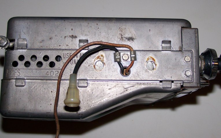
Since Gary private messaged you the rest of us do not know if he answered your question. In case he didn’t, I attached a picture of the left side of my radio showing the two wires and the radio wiring diagram. On my radio the black wire with the fuse holder powers the radio and the brown wire is for the radio illumination and goes to the dash lights.

doug7740
1955 Thunderbird Blue

Radio Right Side View (2).JPG
 

Attachments

  • Radio Wiring Diagram.pdf
    457.4 KB · Views: 12
Last edited by a moderator:
Back
Top