1961- Wiring harness testing

Daddyo

Daddyo

Member
Last seen
Joined
Aug 23, 2022
Thunderbird Year
1961
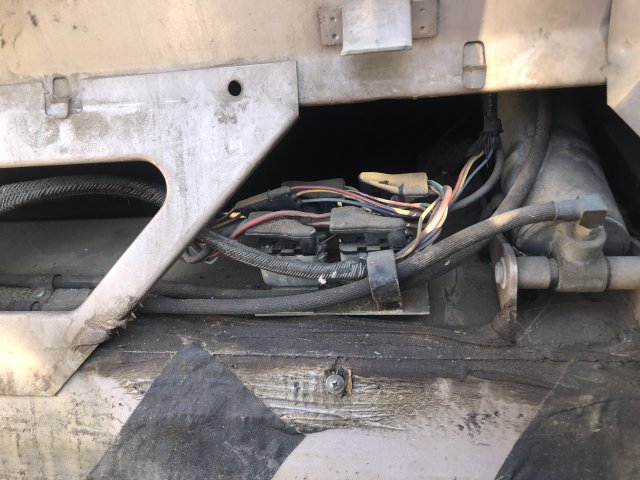
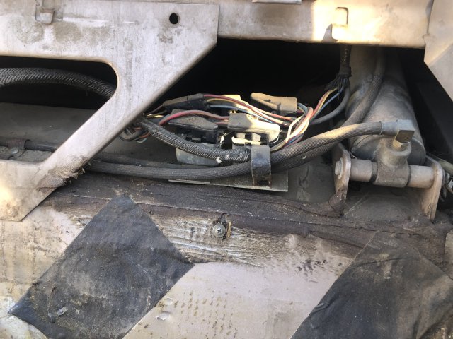
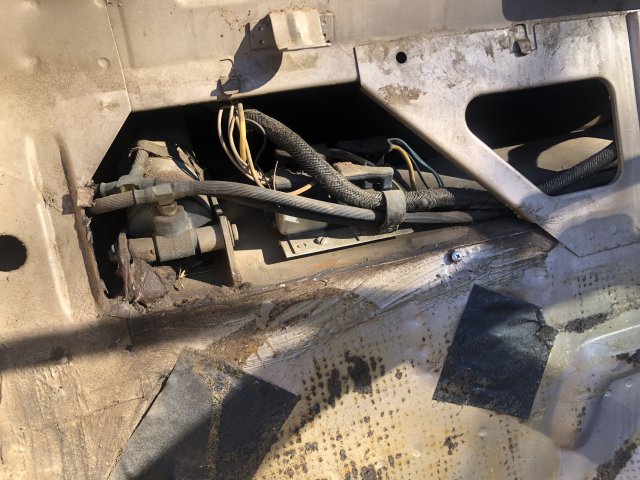
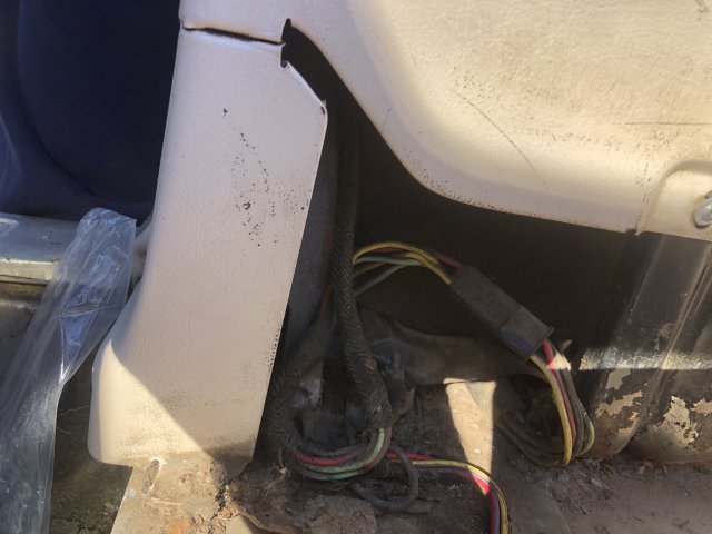
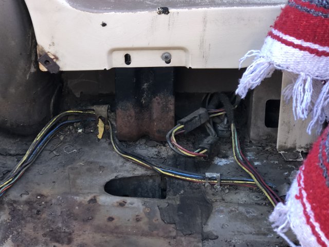
I now have the 1961 Bird up and running... purrs like a kitten, brakes work, transmission is clean and working, etc. Now it is time to check some of the wiring. The fuel sender/gauge works, as well as the temp gauge, but is there a way to test the wires for other functions without having to go as far as getting a whole new wiring harness?
 
Last edited by a moderator:

This site contains affiliate links for which I may be compensated. As an eBay Partner, and Amazon Associate I may be compensated if you make a purchase at no cost to you.

What systems are you looking to test? Wiring harness can be repaired instead of replaced.
What doesn't work?
 
The speedo, clock, windows, locks, and convertible top all don’t work. One of the turn signals comes on (both front and rear) but but brake lights don’t. Haven’t checked on the headlights yet.
 
I'm afraid you will have to trace each circuit individually. I'm going to assume you have or going to purchase a wiring diagram that will help identify each circuit including color codes. Most likely you will find corroded connections that need to be cleaned and then protected wit di-electric grease. A halfway decent multimeter will be your best diagnostic tool. They are not expensive but invaluable in diagnosing electrical issues.
 
So, the speedo is not electric. The clock is easy to pull out and test. (It's probably dead) Start at the fuse box and like @Ward 57 said, start cleaning. You could have blown fuses or bad relays.
 
So, the speedo is not electric. The clock is easy to pull out and test. (It's probably dead) Start at the fuse box and like @Ward 57 said, start cleaning. You could have blown fuses or bad relays.
Gotcha. I just received the color wiring harness mini poster and I plan on getting started when the weather gets a bit better tomorrow. Any recommendation as to where exactly to begin? I've lowered the side windows manually, and haven't tested the motors yet. The wiring looks to be intact and complete, and the switches look good as well. I'll post photos tomorrow so you all can see what I see. I really want to get the convertible top frame folded back, but I'm afraid that's going to be a massive project.
 
Start at the safety circuits first. Lights especially. With the old glass fuses check each one for continuity as sometimes it's hard to tell if the fuse is blown or not. Sometimes if they are good just spinning them in the holder cleaning and re-establishing the connection. Then make a check list of the things you want working first Like the power windows. That is assuming the starting and charging systems are in order.
Leave the top for later, I know you want to see it working but it's not critical at this point.
 
Ok. This is a list of the things that currently work:

Both front headlights on each side work
Driver's side turn signal
Drivers' side rear running light
-Passenger side front turn signal comes on but doesn't flash
Inside on the dash- turn signal indicators both come on, but the right turn indicator doesn't flash

Not working:

Everything else. :)
 
If this car has been sitting a long time you probably will have to pull all the bulbs and clean the sockets. Maybe even replace the bulbs. Your flashers may need to be replaced as well. I would recommend that you pull a battery cable and then pull all of the fuses and use a .22 caliber brush to clean the contacts in the fuse box.
 
If this car has been sitting a long time you probably will have to pull all the bulbs and clean the sockets. Maybe even replace the bulbs. Your flashers may need to be replaced as well. I would recommend that you pull a battery cable and then pull all of the fuses and use a .22 caliber brush to clean the contacts in the fuse box.
Don't know many that would have that specific brush on hand but the brushes are available at any hardware store with brass, steel and nylon brushes as a pack but your advice is sound. I don't want to preach but di-electric grease on any connection you touch will serve you well.
 
Oh, you're not preaching! I have a VW bus and di-electric grease is a must-have/use on the wiring for that. :) Thanks for the tips and I'll keep you posted. In all honesty, I don't know really how to use a multimeter, so when I get ready to get 'er going, I'll post pics and if you're willing, walk me through it.
 
Oh, you're not preaching! I have a VW bus and di-electric grease is a must-have/use on the wiring for that. :) Thanks for the tips and I'll keep you posted. In all honesty, I don't know really how to use a multimeter, so when I get ready to get 'er going, I'll post pics and if you're willing, walk me through it.
They are not complicated. A simple test light works but a multimeter can check resistance which is critical in tracking down iffy connections. Once you get the hang of it you will wonder why you never got one before especially if you have an old VW bus. those are notorious for bad connections.
 
IMG_2576.JPGI've attached a couple of images. First, the passenger side bulb and gasket are roached. What bulb should I replace it with? Additionally, how to I remove the casing without damaging it to get at the wiring?

Second, I've attached a couple of pics from the drivers side door and the multimeter. What do I attach with what and what setting should I be using? I'm so sorry if I'm coming off as completely inept, but I'm still trying to learn as much as I can. As well as the motor for the passenger side window.IMG_2573.JPG
View attachment IMG_2575.MOV
 
View attachment 24917I've attached a couple of images. First, the passenger side bulb and gasket are roached. What bulb should I replace it with? Additionally, how to I remove the casing without damaging it to get at the wiring?

Second, I've attached a couple of pics from the drivers side door and the multimeter. What do I attach with what and what setting should I be using? I'm so sorry if I'm coming off as completely inept, but I'm still trying to learn as much as I can. As well as the motor for the passenger side window.View attachment 24915
View attachment 24916
That connector shows clear signs of overheating. Most often happens with corroded connections. I'm sure you will find that the caps on the tips of the probes pop off giving you a longer un insulated probes that can then be inserted into the connector to test.
Most light bulbs have their number imprinted on the barrel. I'm sure there is some reference material on which bulbs went where if the bulb itself is unreadable. I'm sure almost any auto parts store also has jumper wires with alligator clips that will come in very handy so you don't have to use both hands when testing. Clip one on a decent ground, the other on the black probe and then you can poke around with the red one easily.
 
Sounds good on all counts. Any input on the rear tail light removal? Also, I'm putting pics up that I could use further input on as well (if you don't mind...)

IMG_2580.JPGIMG_2581.JPGIMG_2582.JPGIMG_2577 (1).JPG
 

Attachments

  • IMG_2577 (1).MOV
    5.7 MB
  • IMG_2578.JPG
    IMG_2578.JPG
    3.4 MB · Views: 2
  • IMG_2579.JPG
    IMG_2579.JPG
    3.4 MB · Views: 2
  • IMG_2580.JPG
    IMG_2580.JPG
    4.2 MB · Views: 1
  • IMG_2581.JPG
    IMG_2581.JPG
    2.9 MB · Views: 2
  • IMG_2582.JPG
    IMG_2582.JPG
    2.4 MB · Views: 2
Ok. Got the alligator clip hooked up (see pic) but I KNOW I'm doing something wrong. I've looked at YouTube videos, and perhaps I'm just completely lost when it comes down to voltage and continuity. I've also included pics of the fuse box under the steering column and some of the wiring. How would I be able to tell if a fuse is blown? The glass would be broken?

IMG_2600.JPGIMG_2603.JPGIMG_2604.JPGIMG_2605.JPGIMG_2606.JPG
 
You can usually see if the fuse is blown. The conductor will be burnt in half. Some of them are small so doing a continuity check ( the upside down 'U' symbol setting on your meter ) will confirm one way or the other.
The setting for DC current is the straight line and a broken straight line under it. Household alternating current has a wavy line.
Those contact clips in the fuse block look pretty corroded and need to be cleaned along with the contacts on the fuse itself.
 
So do I merely touch the wire/contact clips with the positive from the multimeter? In the first pic, I inserted the red connector from the multimeter into the connector from the window. Is that the correct way of doing that?
 
So do I merely touch the wire/contact clips with the positive from the multimeter? In the first pic, I inserted the red connector from the multimeter into the connector from the window. Is that the correct way of doing that?
Yes that is correct. However you will find there will be no current at this point. I'm assuming the connector is for the window motor. The center connector is usually the ground so check that with the ohm setting, you should see resistance on the meter. The other two are the actual power connectors, one for up and one for down. If it is for the switch they should both have power when the key is in the Acc position. The wire diagram should show which color does what the ground wire is usually black.
 
When it comes to power windows you need to have both wires from the multi meter in the connection and then operate the switch both ways. The power and ground switch places to reverse the motor. You won't get a good reading attempting to use the door as a ground.
 
Back
Top