Adding a 1965 turn single sequencer to a 1964

This site contains affiliate links for which I may be compensated. As an eBay Partner, and Amazon Associate I may be compensated if you make a purchase at no cost to you.

Has anyone wired in a 1965 bird sequencer in a 1964 bird? I like how it looks on the 65 and 66 birds and would like to add it to my 64. I already have the sequencer from a 65. Thanks, Larry.
I have a number of customers who have added sequential systems to their 1964 T-Bird. I recommend using the TS-400-64T system for ease of installation.
It works with the "Plasma" LED bulbs that are much brighter than the 1157 bulbs - a bonus safety feature. The reduced current will help your turn signal switch last much longer too. You only need to add two 18 ga wires from the front turn signal lights to the trunk. These signals allow the controller to distinguish between turn signal and brake light mode thus avoiding sequencing the brake lights.

The rear tail light turn signal/brake light socket feeds must be separated for sequential action. This can be done by cutting the original harness or installing a pair of new C5SB-13406-AR '65-66 T-Bird tail light bezel harnesses and C5SZ-14405-P2 pigtails to connect to the controller.

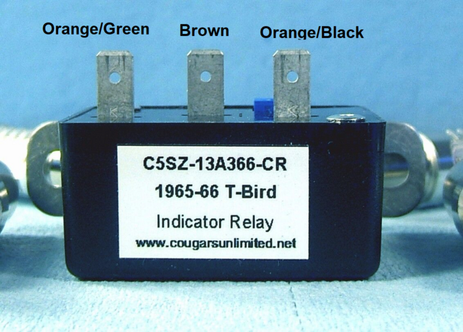
If you choose to use an original style 1965 T-Bird sequential controller, four wires must be run to the trunk: brake switch (18ga) , brake power (12ga), Right front and Left front (16 ga, both controlled by the sequential box). Also, the 3-pin flasher must be removed and the special current sensitive 1965-66 Thunderbird indicator relay (C5SZ-13A366-CR) must be wired into the rear turn signal feed for the sequential controller.

Vic Yarberry
Vic, I'm just about done installing a 1965 sequencer pack on my 1964. Everything seems to be working fine when I put direct power to the orange/green and brown wire at the sequencer/flasher motor. Exactly, how do you wire the turn indicator relay into the turn signal feed? Do you have a schematic of this?
 
I don't have that particular combination diagram drawn up. As noted above, I recommend using a TS-400-64T system - it is easier to install.

Referring to the 1965 Thunderbird diagram, it shows that both the RR (orange/blue 5) and LR (green/orange 9) turn signal switch output wires are tied together to the orange/black (458) wire, to provide the indicator relay input.
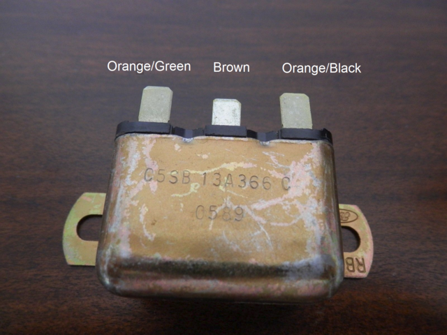
Looking at the indicator relay with the pins up, and the bracket away from you, the pins are oriented: orange/green, brown, orange/black.

1710886571505.png1710887830902.png

The indicator relay brown (694) wire connects to the turn signal switch indicator light input. Indicator light output is directed to the right (red 362) or left (yellow 363) fender indicator lamps.
The indicator relay orange/green wire connects to the orange/green wire in the sequencer pack.
The RF TS switch output (2) connects to the violet (441) wire in the sequencer pack. (Not to the front bulb!) The original RF front bulb white/blue (2) must be disconnected and connected to the sequencer pack (449).
The LF TS switch output (3) connects to the white (440) wire in the sequencer pack. (Not to the front bulb!) The original LF front bulb green/white (3) must be disconnected and connected to the sequencer pack (448).
Note that the brake power is not fed through the turn signal switch on a 1965-66 but controls the brake light relay green/white (475) in the sequencer pack.
Switched 12V power is provided on the red (474) and the relay output is connected to the green 476) in the sequencer pack.
 
Back
Top