1956 directional flasher clicks once

woodeye

woodeye

Active Member
Last seen
Joined
Mar 12, 2021
Thunderbird Year
1956
What does it mean when dir. Flasher only clicks once when changed from neutral to left or right. Lights never illuminate. They did last week but slowly and only a few flashes each time.
Thanks
 

This site contains affiliate links for which I may be compensated. As an eBay Partner, and Amazon Associate I may be compensated if you make a purchase at no cost to you.
Thanks for responding.
Are you talking about grounding the flasher relay itself? The one in the car apaers to be a replacement. It doesn't show any sings of age. The 2 terminals are clean and bright. The case is also clean, no oxidation new looking. There are only 2 terminals with individual wires. One hot and one hot when lever is moved up or down. I did try to ground the flasher case to unpainted bolt. No dif. just one click If you are talking about a bad ground at a bulb wouldn't that only effect that bulb not all of them? Do these cars use a "unique" flasher relay. Mine looks like a generic one you'd get off the shelf at Napa etc.
What parts sources do you guys use. For instance3 I get stuff for my British car from Moss Motors or TRF.
Thanks Jeff
 
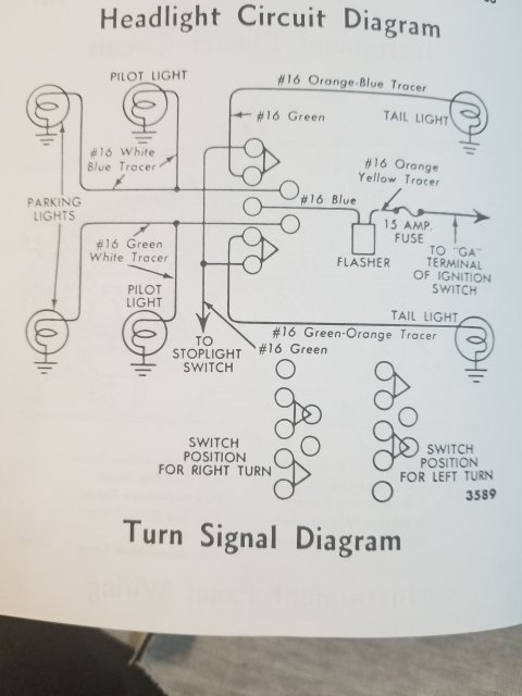
The switch could also be the problem, if you hold up or down on the switch, will it continue flashing. See the attached diagram.
Voltage comes from the battery through the fuse to the flasher, then passes on through the switch to the lights.
Yes, grounding is completed at the light bulb, which would only affect the bulbs.
I removed my switch for cleaning and reassembly was a pain. Only slightly better, new switch cured my issue.
I also put a new flasher in and im thinking they are polarity sensitive. But I can't be sure.
20210409_170129.jpg
 
The switch could also be the problem, if you hold up or down on the switch, will it continue flashing. See the attached diagram.
Voltage comes from the battery through the fuse to the flasher, then passes on through the switch to the lights.
Yes, grounding is completed at the light bulb, which would only affect the bulbs.
I removed my switch for cleaning and reassembly was a pain. Only slightly better, new switch cured my issue.
I also put a new flasher in and im thinking they are polarity sensitive. But I can't be sure.
View attachment 17278
I should specify when wrote switch it is the signal or directional switch. Not the ignition switch
 
Thanks again I think I'm beginning to get it.
Let me put this into my terms and see if I'm on the right path.
Power comes in through the fuse into the flasher relay and up to the dir. sw.. But only when the directional switch in the steering column is moved out of neutral to the rt turn or lf turn position is the circuit to the bulbs completed. Once the circuit is completed the current actually goes through the flasher causing the metal strip inside to heat up and cool down, opening and closing (flashing) the current flow up to the sw. and out to the bulbs on either the rt or lf side.
Your dia. is virtually identical to one in a Red 1956 Ford shop manual pg. 259 the previous owner gave with the car.
Your explanation helped me to make head or tails of it, assuming my description is correct.
I also need to repair/replace the horn wire from the button down and out bottom of the steering column. (See earlier post from Fri. re, "Horn Always On")
I assume when I access the turn sig. sw. that would be the time to deal with the horn wire.
Do you know if that wire is repairable or only replaceable.
Could you suggest a source for parts like the sw,, the relay, or the horn wire etc.
I really appreciate your help.
 
That's correct.
I use one of the US, Thunderbird suppliers, ie. Hills Thunderbird, Casco, Larry's, Prestige. Not sure if they ship globally.
As to the horn wire, the sleeve or cover on mine was frayed, which made it tough to fish in and out, I just replaced it for around $25.
 
Also, my horn wire and the one I ordered, has a bullet connector outside the lower steering column, (I can't recall if that goes to the fender junction block or not) for easy disconnection to remove and reinstall to the horn relay.
Find a couple of the previous vendors and order some parts catalogs, they are pretty helpful and have quite a bit of info in them.

Biddle, could you paste this into the horn thread?
Thanks
 
There are only 2 terminals with individual wires. One hot and one hot when lever is moved up or down. I did try to ground the flasher case to unpainted bolt. No difference, just one click.
Jeff,

You said that on the flasher relay one terminal has power and the other terminal only has power when the turn signal lever is moved out of the neutral position, if that is true you have a defective flasher relay.

Looking at the wiring diagram, available voltage from the ignition switch goes through the orange wire with the yellow tracer, through the 15 amp fuse to the terminal on the flasher relay. So that terminal has available voltage when the ignition switch is turned on. Since the flasher relay is a switch and when current is not flowing through it, the flasher relay is closed and available voltage should be at both terminals of the flasher relay. Since you said that on your flasher relay only one terminal has power that would indicate that you have a defective flasher relay. In other words, when the ignition switch is on and the turn signal switch is in the neutral position, you should have available voltage at both terminals of the flasher relay, both the one with the orange wire with the yellow tracer and the one with the blue wire.

Before you start going down the rabbit hole replacing the turn signal switch and its wiring, remove the flasher relay and bypass it by connecting the two wires together. If the flasher relay is defective, when you move the turn signal lever to the left or right positions the respective turn signal lights will illuminate and remain on.

doug7740
1955 Thunderbird Blue
 
Hey Doug nice to meet you. Thanks for jumping in.
I'll retest that flasher tonight. I was going from recollection and I'm getting on in yrs.
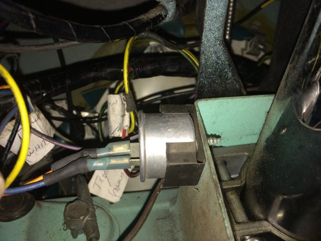
My flasher is just hanging amongst the wires is it supposed to be in some kind of a clip.
 
Jeff,

Under the dash there is a clip that is fastened to the frame just right of the steering column. The original flasher relays were square, however the replacement round relays will also fit into the bracket.

(See attached picture)

doug7740
1955 Thunderbird Blue
IMG_3960.JPG
 
Last edited by a moderator:
Jeff,

You said that on the flasher relay one terminal has power and the other terminal only has power when the turn signal lever is moved out of the neutral position, if that is true you have a defective flasher relay.

Looking at the wiring diagram, available voltage from the ignition switch goes through the orange wire with the yellow tracer, through the 15 amp fuse to the terminal on the flasher relay. So that terminal has available voltage when the ignition switch is turned on. Since the flasher relay is a switch and when current is not flowing through it, the flasher relay is closed and available voltage should be at both terminals of the flasher relay. Since you said that on your flasher relay only one terminal has power that would indicate that you have a defective flasher relay. In other words, when the ignition switch is on and the turn signal switch is in the neutral position, you should have available voltage at both terminals of the flasher relay, both the one with the orange wire with the yellow tracer and the one with the blue wire.

Before you start going down the rabbit hole replacing the turn signal switch and its wiring, remove the flasher relay and bypass it by connecting the two wires together. If the flasher relay is defective, when you move the turn signal lever to the left or right positions the respective turn signal lights will illuminate and remain on.

doug7740
1955 Thunderbird Blue
Doug
I found the the clip thanks.
The 2nd terminal on flasher had only a week glow on tester (bad connection, corrosion?). the hot side was bright. When held them together, bypass the flasher, and moving wand, switch, from left to rt. the tail light, rt or left, lit up. I ordered a new flasher. I'll let you know if that was it. Do you know if the flasher has a polarity? I'd hate to wreck it. I didn't see any marking on the one in there now.
Thanks
 
Jeff,

As I stated before, the flasher relay is a switch and when current is not flowing through it, the flasher relay is closed and available voltage should be at both terminals of the flasher relay. Since you said that when you tested the 1st terminal of the flasher relay with your test light the light was bright and the second terminal was dim, that would indicate that the contacts inside the flasher relay are corroded and the relay is defective. The flasher relay is just a switch and it doesn't matter which terminals you connect the wires to.

doug 7740
1955 Thunderbird Blue
 
Doug thanks for the flasher info. should have my new one Sat. or Mon. I'll let you know how it goes.
Also thanks for the pics. of the steering column. Mine looks like the first pic, like it is all the way collapsed. any ideas on how to get it to move
 
What does it mean when dir. Flasher only clicks once when changed from neutral to left or right. Lights never illuminate. They did last week but slowly and only a few flashes each time.
Thanks
Consider the parts involved…the turn signal switch in the column, the flasher, the fuse and finally the individual bulbs, sockets and wiring. I would begin by checking the fuse using my favorite basic test tool (a test light) to confirm power is going though the line and the fuse is good. Then find the flasher and using the test light confirm power at the flasher when the turn signal is cycled for both left and right. So now you have traced power through the fuse box and the steering column turn signal switch to the flasher itself. Have a speare flasher on hand and swap it out with the current flasher once you know there is power to the flasher. If that does not solve the issue proceed by removing each bulb and again using a test light confirm power to each socket for both the parking light filament and turn signal filament, being careful not to touch the test light probe to the socket wall and base contact simultaneously in the bottom of each socket, which will blow the fuse. Confirming power at each socket contact will tell you the wires are good as well as the individual connection. The last thing is to confirm you have a good ground at each light socket. If only one light didn’t work a bad ground or wire in the harness typically is the culprit assuming the bulb is fine. But since all the lights are not working I presume your problem lies somewhere between the flasher, the signal switch in the column, the fuse and the power wire supplying the voltage. Good luck.
 
Consider the parts involved…the turn signal switch in the column, the flasher, the fuse and finally the individual bulbs, sockets and wiring. I would begin by checking the fuse using my favorite basic test tool (a test light) to confirm power is going though the line and the fuse is good. Then find the flasher and using the test light confirm power at the flasher when the turn signal is cycled for both left and right. So now you have traced power through the fuse box and the steering column turn signal switch to the flasher itself. Have a speare flasher on hand and swap it out with the current flasher once you know there is power to the flasher. If that does not solve the issue proceed by removing each bulb and again using a test light confirm power to each socket for both the parking light filament and turn signal filament, being careful not to touch the test light probe to the socket wall and base contact simultaneously in the bottom of each socket, which will blow the fuse. Confirming power at each socket contact will tell you the wires are good as well as the individual connection. The last thing is to confirm you have a good ground at each light socket. If only one light didn’t work a bad ground or wire in the harness typically is the culprit assuming the bulb is fine. But since all the lights are not working I presume your problem lies somewhere between the flasher, the signal switch in the column, the fuse and the power wire supplying the voltage. Good luck.
Thankyou so much. That was a very logical and detailed explanation of the process.
I have power at the flasher so would that indicate that the fuse is good.
Where are the fuses?
Is there no fuse block?
Does each power feed have an inline fuse.
Where is the main power source?
I get a new flasher from Hills today or Mon. I'll swap them and let you guys know the results
Thanks Jeff
You are most welcome. My recollection is that there was no fuse box on the early baby birds. They had inline fuses for each component under the dash. Depending on what a prior owner may have done, you should find the in line fuse next to the flasher can. a Primary power source was run directly off the ignition switch as I recall but its been decades since I worked on the 55-57 Birds. Mine is a 2005. Sorry I can’t recall but maybe one of our other members can help us on that question.
 
One point to consider, if you decide to access the ignition switch I recommend disconnecting the battery to avoid a shock or frying some wires.
 
Good info. I'll proceed with caution. I think most of the wiring is Unmodified. The connectors and wires show a lot of signs of age. dirt, corrosion, and stiff brittle wires. I may take the instrument cluster out this winter as gauges clock and radio don't work and speedometer jumps all over.
 
I'd recommending buying a master battery switch. They are around only $10. Then you can fiddle and test with a flip of the wrist to connect and disconnect the battery without the hassle of the battery connections.
 
Back
Top