55 Thunderbird Dash Lights Not Working

Notice: This site contains affiliate links for which I may be compensated. As an eBay Partner, and Amazon Associate I may be compensated if you make a purchase at no cost to you. Thank you for your support!
TommyDanger

TommyDanger

Click here to upgrade
Last seen
Joined
Jan 29, 2019
Thunderbird Year
1955
Hey guys! I recently picked up a '55 Tbird and have been fine tuning a couple things. One thing that I can't figure out is getting the dash lights to come on. It has the original 6v setup and I've replaced the headlight switch. Exterior lights, map light, gen and oil lights all work. I've tried adjusting the rheostat without any improvement. My next step is going through the wire harness but I wanted to check and see if I'm missing something. Thanks.
 
Hey guys! I recently picked up a '55 Tbird and have been fine tuning a couple things. One thing that I can't figure out is getting the dash lights to come on. It has the original 6v setup and I've replaced the headlight switch. Exterior lights, map light, gen and oil lights all work. I've tried adjusting the rheostat without any improvement. My next step is going through the wire harness but I wanted to check and see if I'm missing something. Thanks.
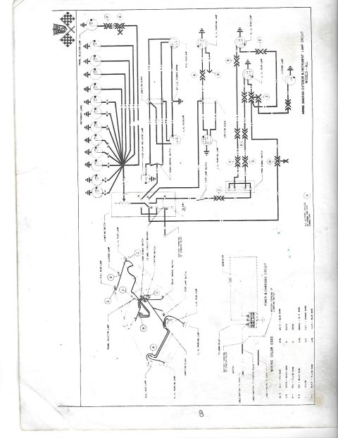
the wire circuit for the instrument lights is a light blue wire with a red stripe. I know there is a fuse on the light switch but I'm not sure if it affects the instrument lights. I personally would check that fuse and verify that the rheostat is working properly. If it's good I would find the Blue wire with the red lead and make sure it's connected at the light switch and then trace it from there. I'm attaching a copy of a wiring diagram from my old Parts Digest book for reference (in case you don't have a diagram)
pg 8 - exterior & instrument lamp circuit.jpg
 
The fuse on the headlight switch only powers the courtesy lamp in the dash and the door jamb switches. If this fuse is blown, check the wiring to the map light and door switches for bare wires especially where the wires exit the kick panels and enter the door jamb.

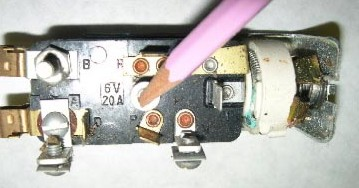
If the dash lights do not work, make sure to rotate the headlight switch while checking. If the dash lights now light, then switch and rheostat are good. If they still do not light, check for continuity between terminal R (black wire) and terminal I (blue wire with red band) while rotating the rheostat. If no continuity, replace the switch or the rheostat if you can find one. On my Thunderbird the rheostat has been eliminated with a jumper wire between R and I terminals.

When you pull the headlight switch knob to the parking light or head light positions, you make an internal connection between the A and R terminals.

upload_2019-3-3_8-15-13.png

The following is the headlight switch terminal wiring.

B - Battery

B Wires
  1. Yellow – Starter relay terminal battery supply
  2. Yellow - B terminal of the ignition switch
  3. Blue/White – Cigar lighter
A - Internal connection from terminal B

A Wires
  1. Green – Stop lamp switch
  2. Blue/Black – Clock
R - Connected to the A terminal in the park or headlight positions

R Wire
  1. Black – Tail and license lights
D – Connected to the B terminal through the 9 amp fuse

D Wires
  1. Green/Yellow – Left door jamb switch for the interior light
  2. Green/Yellow – Right door jamb switch for the interior light
P – Connected to R and A terminals in the park position

P Wire
  1. Black/Yellow – Parking lights
H – Connected to R and A terminals in the headlight position

H Wire

  1. Red/Yellow - Headlights (to the dimmer switch on the floor)
I – Connected to R through the rheostat (resistance changes as the dimmer knob is rotated)

I Wire
  1. Blue/Red – Instrument panel lights

Hope this helps.

doug7740
1955 Thunderbird Blue
 
Doug, that's a great explanation. Do you have one for the ignition switch?
 
Tater SaladMemberLifetime Donor
New
Doug, that's a great explanation. Do you have one for the ignition switch?

I can help a little bit. I went through the wiring circuit diagrams in my book and have broken down what I could find. Strange thing tough, my book does not show the start run circuit? ("S" terminal?) According to my book there are four terminals on the back of the ignition switch. It has been a very long time since I've even looked at the wiring / switches so I can only go by this book right now.

"B" terminal is yellow wire from the Battery terminal of the light switch.
"C" terminal has two wires identified as Blue/Green. one goes to the GEN light circuit and the other goes to the OIL light circuit
"A" terminal has a bunch of wires (less if you don't have power seat / windows or overdrive);
Orange/yellow - goes through a fuse to feed the turn signal flasher.
Black - goes to the overdrive relay.
Blue/green goes to the constant voltage unit to feed the gauges.
Brown - goes to the heater blower circuit
Red - goes to the circuit breaker for the 4-way seat regulator
Yellow - goes to the relay for the 4-way seat-O-matic
Red - goes to the relay for the power windows
"S" terminal in my book shows no connections. I'm pretty sure that would be the start/run circuit. Sorry I don't have the color codes or descriptions. I would have to go pull the old harness out of the box and figure it out. If no one else can help I can check it out and get back to you.
No, Doug. The description you gave is perfect. I assume the "S"terminal should be in the center and goes to starter as well.
My concern is I have a burnt red wire that I now believe is for the power seat. Many thanks for your detailed response. My shop manual wasn't any help with the ignition switch.
My apologies Steven, I didn't look at who posted and made an assumption. Thanks for the information
 
No, Doug. The description you gave is perfect. I assume the "S"terminal should be in the center and goes to starter as well.
My concern is I have a burnt red wire that I now believe is for the power seat. Many thanks for your detailed response. My shop manual wasn't any help with the ignition switch.

I just had a thought. I think the "S" terminal is the start circuit and would feed to the starter relay. The wire for "run" (I don't know the color) would connect to either the "A" terminal or the "C" terminal. Most likely "C" terminal for run. I cannot remember if it feeds to the coil or the starter relay and it probably depends on if the relay has four terminals or three terminals. That way the car would start in one position and then run in the "on" position along with all the other electric things that are operable while the car is running. The reason I think the "C" terminal is because you wouldn't want power to the coil with the ignition switch in the ACCY position.
I can do a little more research if needed. Like I said it's been a long time. I pulled all the wiring out of my car 20 years ago.
 
Last edited:
Thanks for all the help! I’m going to look for the connection point where the dash bulb wires come together and trace that back to the switch. A lot of the wiring behind the dash looks original so I could have a bad connection or loose wire somewhere.
 
Thanks for all the help! I’m going to look for the connection point where the dash bulb wires come together and trace that back to the switch. A lot of the wiring behind the dash looks original so I could have a bad connection or loose wire somewhere.
Or possibly a wire that has the outer casing flaking off. After 60+ years the insulation gets brittle and will crack and fall off especially if anything is moved. Be on the lookout for that also.
 
I'm new to the forum and know this is a late reply. I had the same problem on my '55. It turned out to be that someone had ran the ground wire from the radio into the dash light system. Disconnected this wire (green fabric covering) and the lights worked perfectly.
 
You have some great advice here already, but I'll share that I had some weird electrical issues when i bought my '56. The wiring diagrams I found were not helpful. I found a big, clear, color coded, laminated wiring diagram on ebay that even i could understand. It has helped me alot.
 
Tommy, I had issues with individual dash lights on my 56 T-Bird. These cars are 60 plus years old and all of the dash lighting relies on the chassis / body for the ground. Even well protected cars will suffer with some corrosion that results in a high resistance ground where the lamp base contacts the dash.

I made a dedicated ground wire that I ran to every lamp base, rear of the instrument cluster, base of the headlight switch and a freshly drilled and screwed to a clean part of the sheet metal under the dash. Also make sure that you have a good ground strap between the engine block and the firewall.

This may not solve your individual problem, but I recommend this for all cars of this vintage.

Good luck,
Steve
 
Back
Top