1966 Tail lights wiring harness questions.

Notice: This site contains affiliate links for which I may be compensated. As an eBay Partner, and Amazon Associate I may be compensated if you make a purchase at no cost to you. Thank you for your support!
Ghostrider 67

Ghostrider 67

Click here to upgrade
Last seen
Joined
Sep 14, 2017
Thunderbird Year
1966
Hello all,
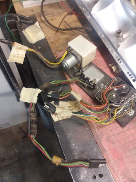
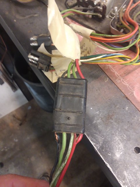
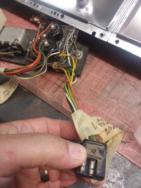
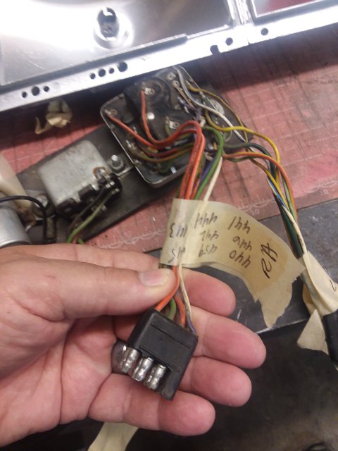
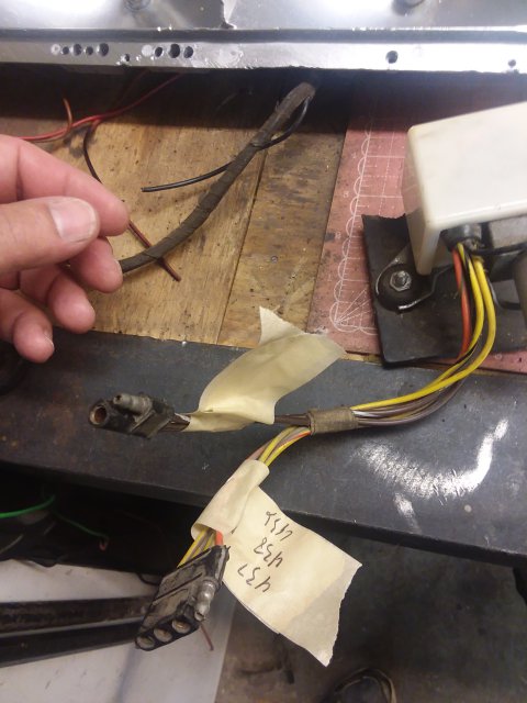
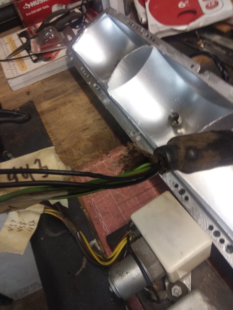
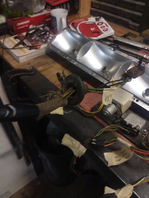
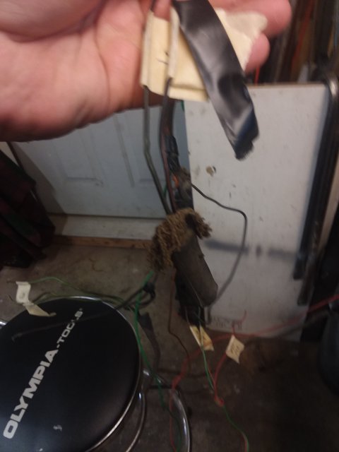
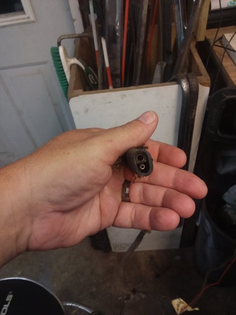
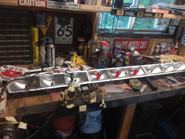
I have a 1966 T Bird tail light system with the rubber patch holding the sequencer, relay and switch, and the old harness that is in poor shape. It's in three pieces and mostly untaped from the factory wrappings. One end has been cut through and I think i'm missing some connectors with pins. I have all 9 of the bulb sockets. What I need is a definitive photo of what the entire tail light harness is supposed to look like. What plugs into what? What plugs into the three units bolted to the rubber plate.
I have the schematics and have figured out the numbers on the wires and the color codes.

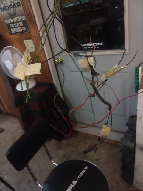
Okay, now, here's the kicker, don't be mad..lol...this unit isn't in a 1966 T Bird. It's in the tail end of my 1967 Dodge Coronet 500. Yes, you read that right. So, what will do is run forwards with the wiring to the turn signal switch and stop light switch. Also to the front park/ turn signals.
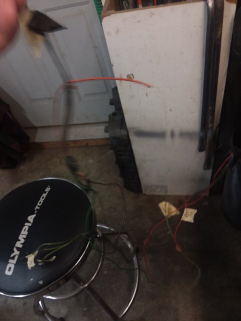
I just have a mess right now on the table of un taped wiring and miss matched plug ends.

Help please!
 
There are two different 1966 T-Bird wiring setups: early and late.
The early cars use a triangular 3-pin stop lamp relay with an external ground. It has red, green, and green/white wires.
The late cars use a flat 4-pin stop lamp relay that includes the ground.

Both have a 6-pin and 8-pin rectangular connector.
Also both use a flat 4-pin connector with orange/green, yellow, yellow/red, and yellow/black wires.

Shown below is a set of pigtails that I had made up for repairs to the late '66 harness. The 1965 - early '66 is similar.
1658420305938.png
 
Does your car also have the 3-pin T-Bird indicator relay?
This current-sensitive indicator relay is required to operate the dash indicator lights.
It is calibrated to click when 4 lights (3 in the rear, and one in the front) are on.
If you review the schematic, it is wired in series with the power feeding the sequencer in the trunk.
If you need additional help understanding how to make this system work in your car, please contact me.
Vic Yarberry
info@cougarsunlimited.net
 
I have this one: The one on the right side of your photo.
 

Attachments

  • 20220721_130816.jpg
    20220721_130816.jpg
    1 MB · Views: 12
  • 20220721_130823.jpg
    20220721_130823.jpg
    1 MB · Views: 10
  • 20220721_130841.jpg
    20220721_130841.jpg
    1 MB · Views: 9
  • 20220721_130847.jpg
    20220721_130847.jpg
    955.7 KB · Views: 9
  • 20220721_130852.jpg
    20220721_130852.jpg
    1 MB · Views: 9
  • 20220721_130918.jpg
    20220721_130918.jpg
    798.1 KB · Views: 9
  • 20220721_130925.jpg
    20220721_130925.jpg
    760.2 KB · Views: 9
  • 20220721_130931.jpg
    20220721_130931.jpg
    722 KB · Views: 8
  • 20220721_130935.jpg
    20220721_130935.jpg
    654.3 KB · Views: 8
  • 20220721_130937.jpg
    20220721_130937.jpg
    642.1 KB · Views: 8
  • 20220721_130940.jpg
    20220721_130940.jpg
    695.2 KB · Views: 9
  • 20220721_130951.jpg
    20220721_130951.jpg
    2.1 MB · Views: 12
You have the late '66 T-Bird system with the 4-pin flat stop lamp relay.
The T-Bird sequencer has an additional 2-pin connector with brown, brown/white wires.
It is solely used to drive the motor around to the start position after the turn signal lever is returned to the neutral position.

If you review the schematic, you will find:
1. The output of the stop lamp switch feeds the 18 ga green/white on the stop lamp relay.
2. The stop lamp relay 14 ga red wire needs +12V. Use a 15A circuit breaker.
3. The stop lamp relay output, 14 ga green, feeds the 14 ga green/white wire on the 6-pin relay connector.
4. Both R & L rear signal feeds from your turn signal switch connect to the orange/green wire on the motor-driven sequencer.
5. The R & L front light wires from your turn signal switch connect to the 8-pin relay connector, violet and white.
6. The white/blue and green/white wires from the 6-pin relay connector feed the R & L front turn signal lights.
Note: They must not connect to the turn signal switch directly.
7. The rear tail light connections are shown in the schematic: green/orange, green/red, green/black are LH,
orange/blue, orange/white, and orange/red are RH.

Note: It is highly recommended to convert the rear lamps to LEDs because of the high current that is drawn by incandescent 1157 bulbs.
I'm not sure how robust the Dodge turn signals switches are but this is a failure point in the Fords with 6 tail lights.
Well, all of that is very helpful! Thanks. As for the turn signal switch it is part of 2004 Audi A-6 Quattro Allroad dash that is in my Coronet. So I'll be hooking into that turn signal switch, for which I have the correct schematics to ID the right wires to connect to.

The three devices on the rubber pad are what? The turn signal switch and motor, the stop lamp relay and the sequencer? Or?
The parts on the rubber pad:
Motor-driven sequencer (4-pin flat connector and 2-pin flat connector)
Stop lamp relay (4-pin flat connector, - red, green/white,green/black wires)
Turn signal relay (8-pin and 6-pin connector)
 
Hi! Not sure whether this should be a separate thread but it seems like the subject of this thread still applies. My first car was a ‘66 Bird with the sequential turn signals. I don’t have that beautiful car anymore ;-( but I do have an almost perfect 2010 Lincoln MKX with taillights that lend themselves to the same sequential system. Anyone have any insight on whether this would be doable? Maybe I should be looking at the late model Mustang sequential harness as a possible start?
 

Attachments

  • 93252F10-4CD1-4977-A332-134E025BB208.jpeg
    93252F10-4CD1-4977-A332-134E025BB208.jpeg
    551.6 KB · Views: 1
Technically, it is possible. The 2010 owners manual shows that the rear uses two incandescent 3157 bulbs per side.
However, your picture shows a single piece bezel (LEDs?) not the two piece bezels advertised on Ebay.

The two-piece inner bezel on each side would need an addition socket and divider installed to provide separate light segments.

Another issue is that these cars typically use an electronic body module that controls and monitor the lights.
Any additional bulbs would need to draw approximately the same amount of total current to avoid an error code.
LED bulbs are probably the best solution.

A different flasher may be required to slow down the flasher rate to about 60 flashes/minute to allow enough time for
your eye to distinguish the sequence.

Finally, in order to avoid sequencing the brake lights, 2 wires from the front turn signal bulbs would need to be routed
to the controller.

If you are interested in pursuing this project, contact me offline or send a private message.
 
Back
Top